
A classic undergraduate project one may build in an embedded systems, mechatronics, or robotics course is a line following robot based on PID control. This ties together a lot of key ideas in mechanical, electrical, and computer engineering and is a good exercise in cross-functional design that one encounters in industry. Here I describe the theory and design of such a line following robot I built for my undergraduate mechatronics final project. This project is implemented using an Arduino based around PID (Proportional Integral Derivative) control system. The robot is designed to complete a determinisitic (and star wars themed!) obstacle course, as will soon be described.
Skip to the very end section Demo to see the robot in action!
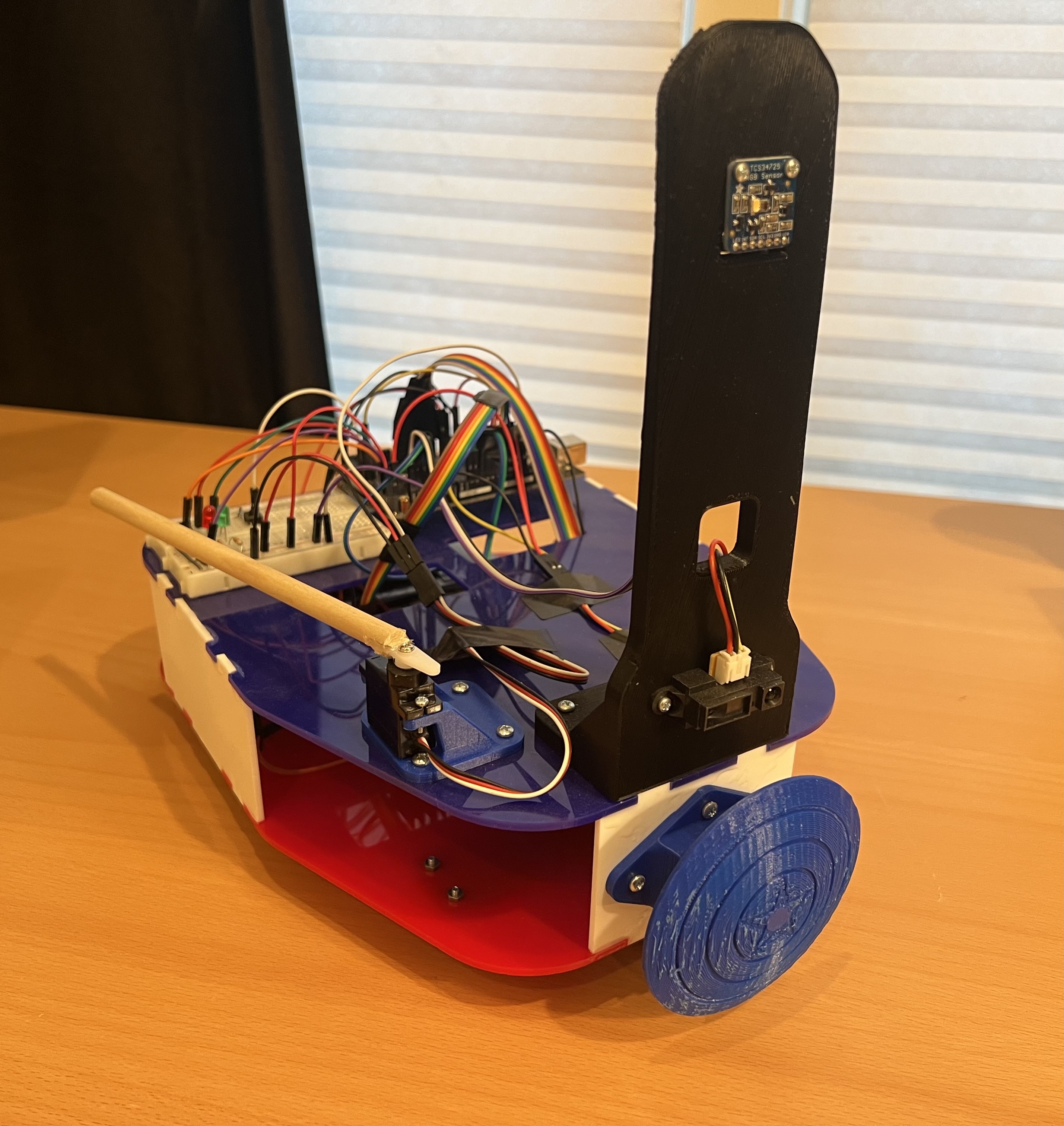 Figure 1 - The fully assembled robot.
Overview
Before diving into the theory and design, let’s set the stage with what this robot was actually requied to do. Below lists the design constraints and overall obstacle course objective to be carried out by the robot:
- The robot must autonomously complete a sequence of tasks on the designed course. The course cannot be modified in any way.
- There is a starting point near the right-center of the course where the black line starts. Your robot needs to start in that area.
- First you must navigate through the corridor of the first order base. (watch out for the two garbage chutes). One possible path is marked with 1” wide black tape. Your robot must move through this corridor.
- At the end of this corridor, four stormtroopers are standing guard. You must knock them down. If they get back up – run.
- After you pass the guard station, there is an unmarked passage to the armory on your left. When you enter the armory, you will find 5 light sabers mounted to the back wall. Two will be captured Jedi light sabers. These glow green. Three are Sith light sabers. These glow red. If you are endowed with the Force, you may press the handle of a Sith light saber, and it will turn from red to green. If you press the handle of a Jedi light saber, you will send it back to the dark side. You must get all 5 light sabers to glow green.
- Once all 5 light sabers are green, you must escape the armory. No part of your robot can remain in the room. The light sabers will take control of the ship and destroy all evil aboard. They may look strange while this is happening.
- You can backup and retry as much as you want.
- Teams will be given several runs on competition day. Best run counts.
If you couldn’t tell, the theme for this course is Star Wars. See the Demo section to see this robot wield the force. Now let’s get into the details on the theory and design aspects of this design.
System Structure & Operation
The block diagram of the PID robot is shown below in Fig. 2. As can be seen, the robot is based on an Arduino Mega 2560 as the main microcontroller (MCU). The MCU interfaces to various digital and analog blocks used for obstacle sensing, robot control, actuation, and motion. The robot is based on a differential drive architecture, meaning only the PWM of the rear wheels are used to control the heading/steering of the robot, which is balanced on the front with a ball bearing.
 Figure 2 - Block diagram of the designed PID line follower robot. Grey blocks indicate control elements, while blue blocks indicate sensing elements.
Robot Assembly
The mechanical chassis was designed in solidworks and is shown in Fig. 3. 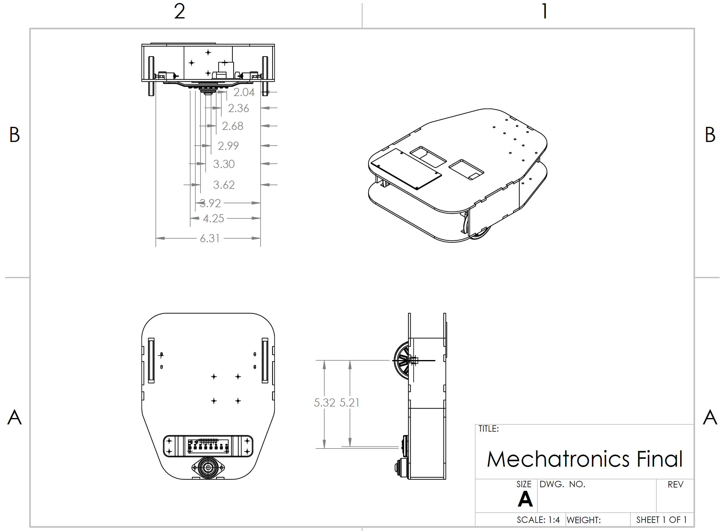 Figure 3 - Mechanical assembly drawing of the robot chassis. Dimenions are optimized for component placement and also the position of the wheels with respect to the axis of rotation (required for achieving stable PID control).
The chassis was laser cut with acrylic sheets and glued together. The sensor mounting components are separately 3D printed and screwed into the acrylic cahssis after assembly. This allowed the design to be modularized and each actuation/sensing arm to be fine tuned to precise mechanical dimensions in order to optimize performance on the obstacle course.
Below highlights robot assembly after everything was cut and the block digram/wiring was decided. 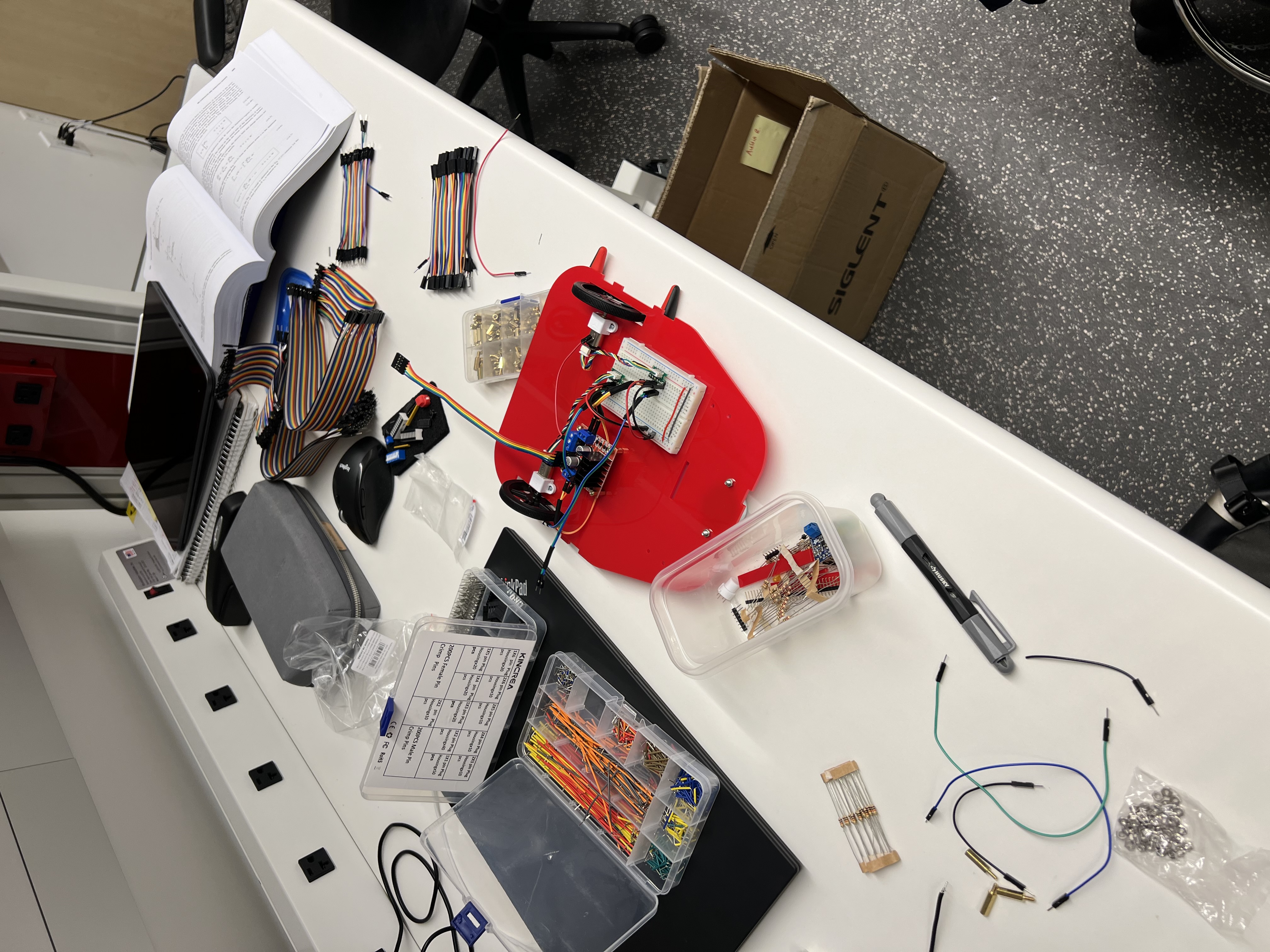 Figure 4 - Robot base being assembled with the wheels, motors, encoders, H-bridge, and breadboard used to breakout to MCU control logic.).
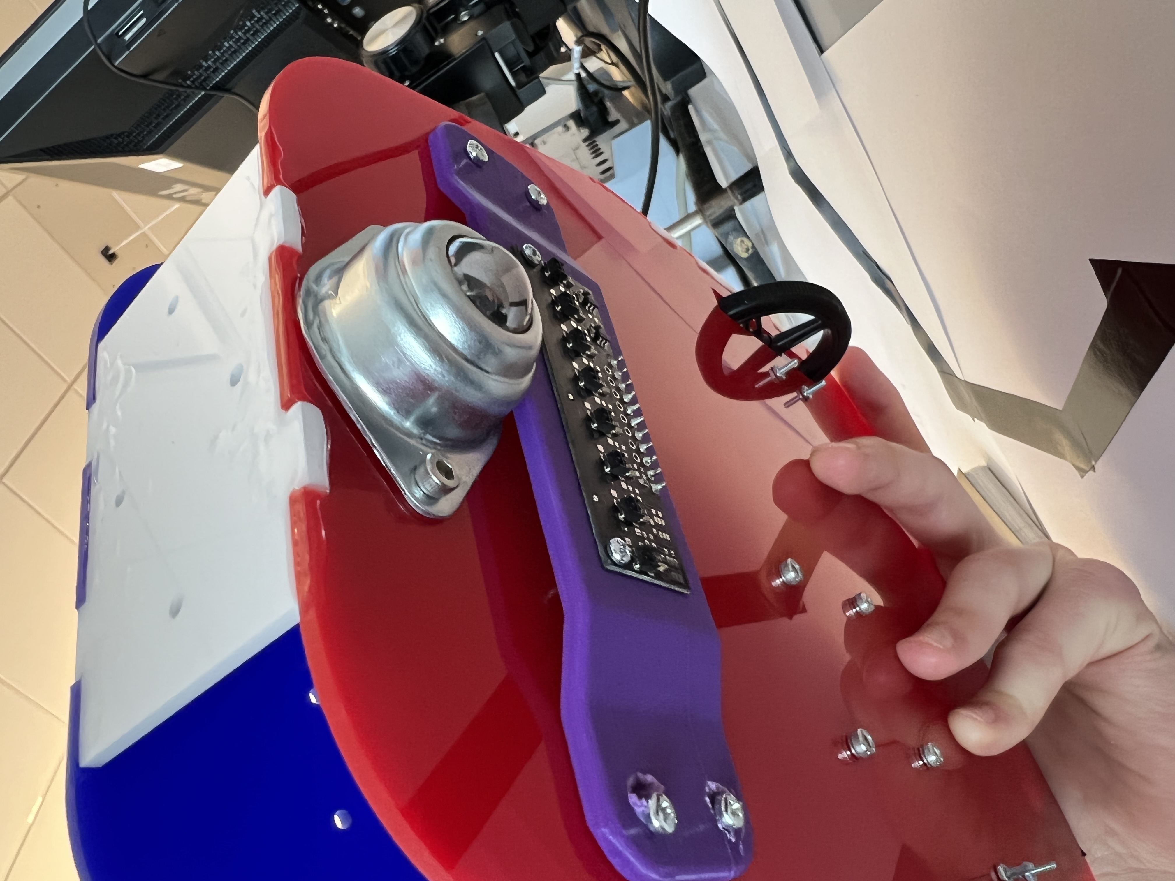 Figure 5 - Robot base being assembled with the wheels, motors, encoders, H-bridge, and breadboard used to breakout to MCU control logic.
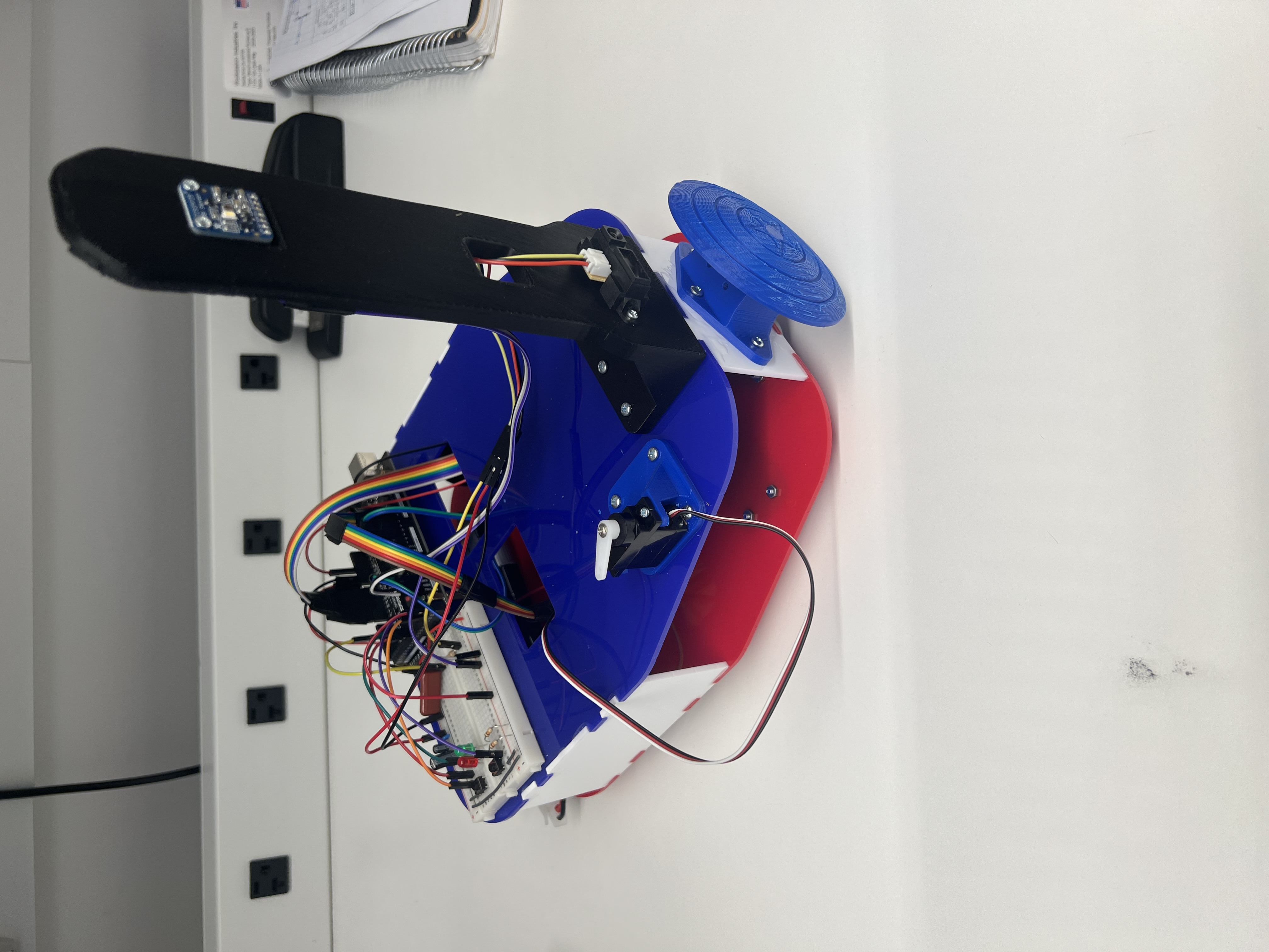 Figure 6 - Robot fully assembled and wired up (guard knocking stick not applied to the servo motor yet).
PID Line Following
PID line following is a technique used in robotics to guide a robot along a pre-defined path or line. The robot is equipped with sensors that can detect the line and provide feedback to a control system, which uses a PID algorithm to adjust the robot’s steering in real-time.
The process of PID line following involves continuously measuring the distance between the robot’s sensors and the line, calculating an error value based on that distance, and then adjusting the robot’s steering to keep the robot on the line. The proportional, integral, and derivative terms of the PID controller are used to adjust the steering in response to changes in the error value.
In a simple PID line following system, the proportional term might adjust the steering angle in proportion to the error, the integral term would accumulate the error over time, and the derivative term would adjust the steering based on the rate of change of the error.
By tuning the PID gains, the system can be optimized to keep the robot on the line while minimizing overshoot, oscillation, and other undesirable behaviors. PID line following is commonly used in robotics competitions and industrial automation applications, where precise control of a robot’s movement is essential.
What is PID Control?
PID control stands for Proportional Integral Derivative control, which is a widely used control algorithm for controlling systems in various engineering and scientific fields. A PID controller continuously calculates an error value \(e(t)\) as the difference between a desired setpoint and the current process variable and applies a correction based on proportional, integral, and derivative terms, hence the name. These terms represent the respective contributions of each control strategy. In Fig. 7 below, the overall structure of a PID control system is listed:
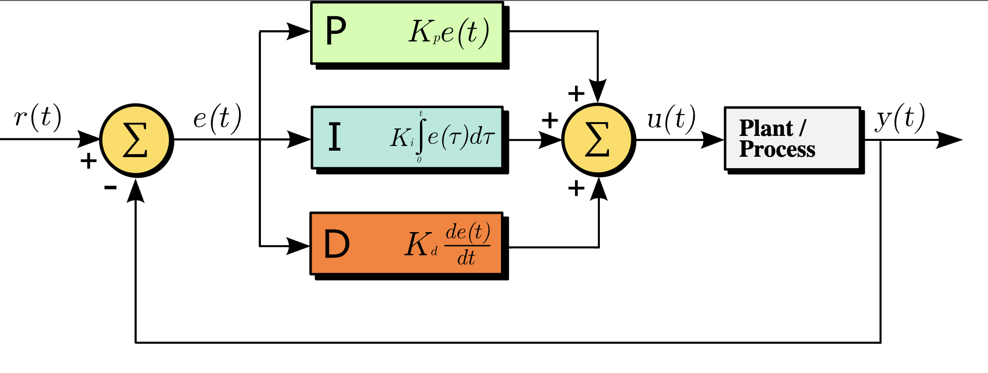 Figure 7 - A block diagram of a PID controller in a feedback loop. r(t) is the desired process value or setpoint (SP), and y(t) is the measured process value (PV) 1.
The proportional control term mostly controls the response time of the control loop. Strictly speaking, a larger vlaue of \(K_p\) means the response time will be faster. This term is proportional to the current measured setpoint error. This means the magnitude of the correction is proportional to the magnitude of the error. A large measured error means a large positive response term will be applied to the system control to bring the measured process value closer to the setpoint such that the error residual is zero. The speed at which this occurs depends on the loop bandwidth of the system which is related to the value of \(K_p\). Note that \(K_p\) must be set to achieve a specific damping, while maintaining control loop stability.
The integral control term is used to improve the steady state response and eliminate steady state error (over time). This term is proportional to the accumulated error over time. So the goal of the integral term is just to eliminate residual errors in the steady state. Some benefits of integral control: Some challenges of integral control are:
- Computing the integral term.
- Integral “windup” - condition where a large change in setpoint occurs and the integral term accumulates sufficient error during the rise (windup), thus overshooting and continuing to increase as this accumulated error is unwound 2.
- Can lead to oscillations/instability at high \(K_i\).
The derivative control term is used to improve the transient response, specificially to eliminate overshoot. This term is proportional to the rate of change of the error. The derivative term is mainly used to best esimtate the future trend of the setpoint/process-value error based on the current rate of change of the system. The more rapid the change in the process value, the greater the controlling effect of the derivative term. Some challenges of derivative control:
- Computing the derivative.
- The derivative control is prone to being impacted by noise coupled into the system observables.
- The derivative term can lead to instability easily in the case of dramatic changes in setpoint.
In any application, finding the correct PID terms (via PID tuning) is an iterative process. For a line-following robot, the PID parameters are heuristically tuned in order to achieve the desired balance of robot speed, correction response time, damping, and control stability.
PID Code Structure
For this robot, the code structure in C is described below. For simplicity, the integral term is omitted as there is not a need to eliminate steady state errors to zero in this application to obtain solid line following performance. This means it is really a PD controller guiding the line following logic, and makes the tuning much easier.
Recall from previous sections that the setpoint here is a measure of reflectance picked up from the reflectance IR sensor on the underside of the robot. Here, we desire the robot to be centered over the black line. That means that the IR signals emitted from the sensor should be looking for areas of minimum reflectance. The setpoint should be the point of minimum reflectance, where light is not reflected. In this case that is the black line, as the white surface will have a higher reflection of light to the sensor array. The sensor used in this robot has 8 different IR sensors, and each feeds an ADC on the main MCU. Each sensor array reading is combined in each sampling period with a weighted average scheme. A value of 0 would correspond to the left-most sensor having minimum reflectance, while a value of 7000 would correspond to the right-most sensor having minimum reflactance. Thus the middle of the sensor array would correspond to a reflectance of 3500. This is our desired setpoint for the robot to adhere to.
1
2
3
4
5
6
7
8
9
10
11
12
13
14
15
16
17
18
19
20
21
22
23
24
25
26
uint16_t setpoint = 3500; //desired steady-state setpoint for the robot to maintain

void PID_follow() {
  uint16_t pos = qtr.readLineBlack(sensorValues); //read in 8x8 reflectance sensor
  int16_t error = setpoint - pos; //compute positional error
  P = error; //proportional
  D = error - lastError; //derivative
  lastError = error;
  int16_t motorSpeed = Kp * P + D * Kd; //update motor speeds
  int16_t motorSpeedA = baseSpeedA + motorSpeed; //add correction to left motor
  int16_t motorSpeedB = baseSpeedB - motorSpeed; //subtract correction from right motor
  //contrain updates to the min and max motor speeds
  if (motorSpeedA > maxSpeedA) {
    motorSpeedA = maxSpeedB;
  }
  if (motorSpeedB > maxSpeedB) {
    motorSpeedB = maxSpeedB;
  }
  if (motorSpeedA < 0) {
    motorSpeedA = minSpeedA;
  }
  if (motorSpeedB < 0) {
    motorSpeedB = minSpeedB;
  }
  forward(motorSpeedA, motorSpeedB);
}
PID Tuning
PID tuning is the process of adjusting the PID parameters (\(K_p\), \(K_i\), \(K_d\)) until a desired control system performance is met. The process of adjusting these involves changing the parameters until the system provides an optimal response to different inputs and disturbances. This process can be done manually, as is done in this project, or automatically using software tools that analyze the system’s response and adjusts the parameters accordingly. The methodology of the tuning depends on the complexity of the system, resource availability, and the desired level of precision and control. In this case, the \(K_p\) and \(K_d\) are simply adjusted until the line following system is able to operate with fine precision, speed, and maintain stability. Below shows an example course used to calibrate the PID control to gurantee optimal line following performance on the obstacle course.
Obstacle Course Traversal
Now that the design and theory have been covered, the robot can now be seen in action with full force (no pun intended). To remind yourself of the course rules, please see the Overview. On top of the PID control structure, the robot also needs to be able to reliabily detect distance with the front-facing IR sensor and precisely turn clockwise or counter-clockwise. Both of these features involving linearizing over a set of discrete calibration measurements, and is not in the scope of this post. Additionally, functions to control the speed and polarity of the motors need to be well defined. One challenge is getting smooth and stable line following performance at a high motor driver PWM - this requires a lot of PID tuning!
Demo
This robot ended up scoring the fastest amongst the competition in the field with a completion time of 43s!