
Overview
Modern wireless systems use transceiver building blocks that have tightly coupled functions in order to improve speed, reduce size, enhance coverage, and lower cost. One of the core ideas behind smart antennas is that of spatial processing. Spatial processing involves the detection of the direction of arrival (DoA) of a signal of interest (SoI) by measuring time deltas of the signals impinging on the antenna elements. Special digital signal processors (DSPs) are then used to adjust the excitation signal’s gain/phase/delay in real time so as to dynamically synthesize a radiation pattern which focuses on the SoI and nulls the non-SOIs.
Cellular Radio Systems
One of the driving forces of smart antenna systems over the years has been the increasing requirement to enhance capacity as the number of services and subscribers in cellular systems grow larger. Capacity is fundamentally limited by the finite number of frequency bands and channels which must be reused in order to service users in a cellular system. As a result, engineers have had to come up with and improve upon different multiple access techniques to satisfy capacity requirements. Smart antenna systems allow cells to re-use frequency bands/channels at a smaller cell repition intervall by helping to mitigate leakage and degradation of SINR to neighboring cells. Smart antennas also help maintain higher throughput at larger distances by the use of beamforming to enhance coverage to users at the cell edge, allowing more link margin to afford the use of higher order modulation schemes further from the base-station.
Omnidirectional Cellular Systenms
The omnidirectional cell structure was the first implementation of the cellular system concept, whereby a region is divided into adjacent cells with each cell containing a base station having an antenna transmitting on specific bands/channels to users within the cell. Neighboring cells are using frequencies that sufficiently differ from each other in order to avoid cell-to-cell interference with other base stations and users. Of course, frequency is a finite resource and must be utilized by other serving cells as well. As can be seen in Fig. 1 below, cells with the same color are utilizing the same frequencies, however, there is sufficient cell separation between the identically colored cells. This separation is dependent on SINR requirements amongst adjacent cells. Since these initial systems used omnidirectional antennas, the neighboring cells would suffer to unwanted interfering signals which could cause receiver desense, limiting coverage & throughput within a cell. This effect is additive, as more users enter a cell the interference also increases, thus reducing capacity.
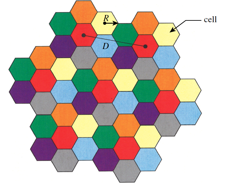 Figure 1 - Example cellular system structure with 7 cell reuse 1.
One of the early mitigations to the problem of the purely omnidirectional cellular system is the use of cell splitting. Cell splitting subdivides a dense cell into multiple microcells, with each microcell having its own base station. The downside of this concept is the severely increased costs of having this many base stations per cell.
Another improvement upon omnidirectional systems is the use of sectorized antennas, whereby a cell is subdivided into three sctions with each having $120^{\circ}$ coverage. This technique allows more frequencies per coverage area by reducing adjacent cell interference. This is highlighted in Fig. 2 below, where it can be observed that sectoring cells allows for the base stations LOS coverage zone to be in the nulls of adjacent base stations.
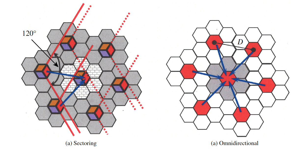 Figure 2 - Cochannel interference of sectoring (a) and omnidirectional (b) cellular systems 1.
Smart Cellular Systems
Sectoring antennas provided an ok first step to the capacity problem cellular systems faced as users and services continued to increase. That being said, sectoring could only help mitigate the problem so much before similar issues began to arise. The solution to this problem which system designers began to investigate involved utilizing a system that could dynamically sectorize a cell, hence the development of smart antennas. As noted in 1, it is not the antennas that are smart but the comnbiation of digital signal processing along with antennas that make the system smart.
Smart antennas esentially are an extension of sectoring in which a cell’s coverage is split into a set of bems through the use of adaptive antenna arrays. This allows base stations to focus their energy towards specific users and also null interfering/unwanted signals. This allows for substantial capacity improvement by allowing for more complex modulation schemes to be transmitted to UEs over larger distances, and also maximizing receiver sensitivity on the base station side due to SINR improvements. Smart antennas operate as eithr switched beam or adapative arrays (Fig. 3). Switched beam systems switch the beam pattern from a set of beam orientations depending on user position. Adaptive systems synthesize patterns to point beams directly at intended users and also create nulls on interference sources.
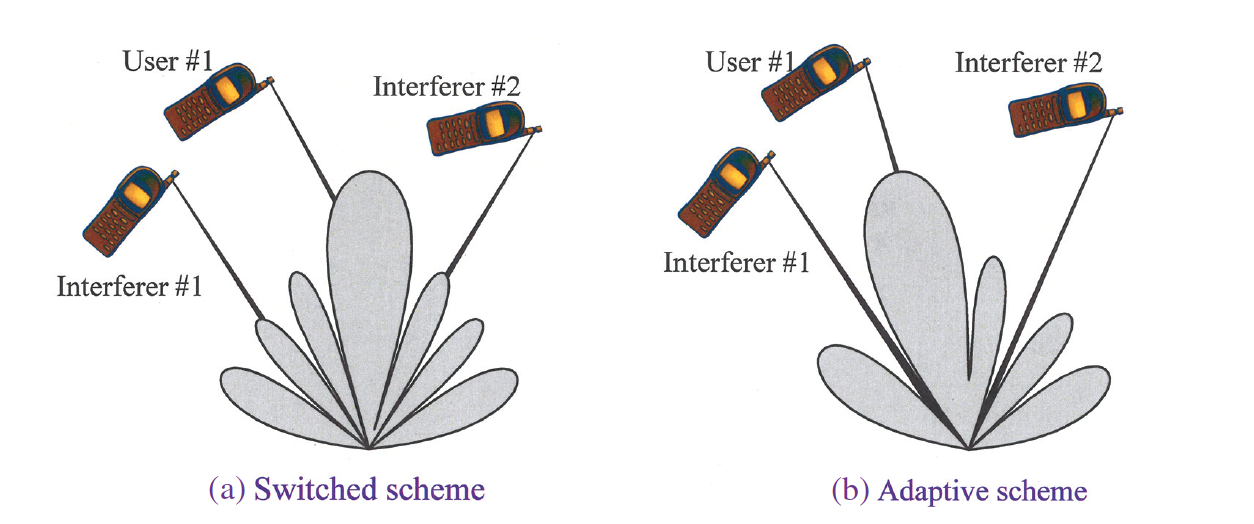 Figure 3 - Switched-beam and adaptive array schemes 1.
Adaptive Antenna Arrays
Adaptive antenna arrays are superior in performance to switched beam systems, however their design and implementation is much more complex. That being said, the increases in capacity, range, and SINR to neighboring cells maks it worth the extra development. Since adaptive antenna arrays control the radiation pattern specific to a given coverage area, they provide a much greater capacity improvement over switched beam architectures. Additionally, adaptive arrays improve wiresless system and adjacent frequency coexistence by the use of dynamic pattern nulls placed on interfering signals.
Fig. 4 below provides a simplified block diagram of an adaptive array system consisting of $M$ antenna paths and a central DSP unit which is controlling the weights $w_{\text{M}}$ (amplitudes/phases) as a function of the computed DOA extracted from the baseband signal information sampled and sent by the analog-to-digital converter (A/D).
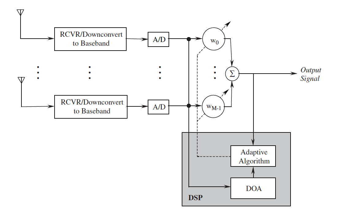 Figure 4 - Switched-beam and adaptive array schemes 1.
Signal Propogation Effects
Smart antennas help to mitigate non-idealities introduced by the wireless channel existing between a base-station and mobile device. The channel is a dynamic entity which introduces multipath fading, delay-spread, and other noise sources into a wireless link which can limit range and throughput if not dealt with.
Multipath arises natrually due to signal reflections in the path between transmitter and receiver. This causes some signal components, or copies of the same signal, to have an additional path length relative to a primary signal coomponent. This causes a phase shift relative to the primary signal and can cause receiver performance to suffer by introducing destructive interference (deep fade) or timing errors due to delay spread between sequential received data symbols. The multipath concept is simple and the time-domain represenation is shown in Fig. 5. This figure is simplified and in reality there may be some additional amplitude distortion or noise also present on either of the direct or reflected signals once it reaches the receiver.
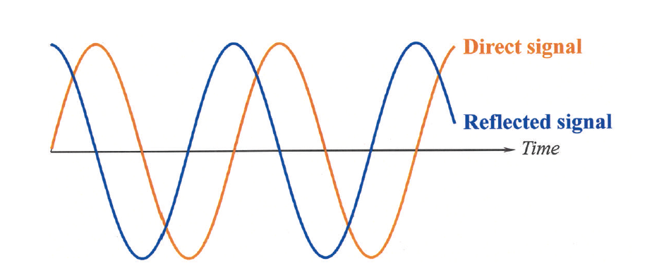 Figure 5 - Time-domain representation of a multipath signal having a time-delay (phase shift) relative to a line-of-sight signal component 1.
Deep fading - the cancellation of a primary signal by an $180^{\circ}$ phase shifted multipath replica - is shown in Fig. 6. There are different types of fading, and a channel’s fade profile is rapidly changing as a function of time and 3D space.
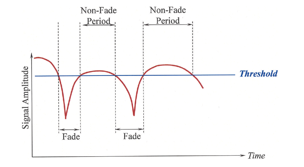 Figure 6 - Received signal amplitude vs. time as a result of fading due to channel effects 1.
Adaptive arrays can mitigate the problem of fading by using DSP mechanisms to help null multpath directions.
In addition to fading, multipath leads to a problem known as delay spread, where the bits of the delayed signal overlap in time with the bits of the primary unreflected signal and leads to a form of distortion known as intersymbol interference (ISI). When ISI occurs, the receiver’s bit-error-rate (BER) increases rapidly and leads to coverage and throughput drops. This is highlighted in Fig. 7.
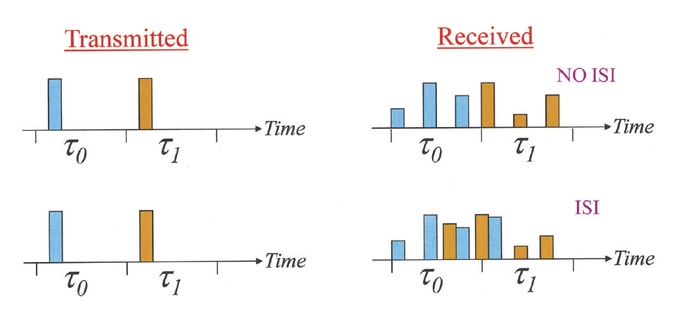 Figure 7 - ISI and delay spread caused by multipath 1.
The last type of signal non-ideality to mention is that of cochannel interference, which occurs when a user’s signal interfer’s with a nearby cell having the same set of utilized frequencies. This is most salient in omnidirectional cells. Smart antennas mitigate this problem by the use of dynamic nulls, thereby improving cochannel interference and allowing a denser frequency reuse plan. This greatly improves capacity and lowers deployment cost. Note that cochannel interference can also occur between different wireless systems if that utilized frequencies are either shared or somilar enough. For example, Bluetooth & WiFi systems must share the 2.4 GHz ISM band in time and often limit each other’s max performance in terms of rate vs. range and/or latency due to retransmissions caused by signal collisions. Additionally, WiFi can have interference on cellular and vice-versa due to non-linearities (power amplifier harmonics, intermodulation distortion products) having transmit leakage that fall in the other systems passband. A popular example of this in mobile phones is that of LTE FDD Band 13 (746-756 MHz) having a second harmonic directly on top of GPS L1’s passband (1575 MHz). Additionally, out of band signal leakage from systems sharing frequency borders is a common issue in practice, especially in systems with collocated radios (phones, smart watches, cars). An exmaple of this is LTE TDD Band 40 (2300-2400 MHz) sharing the frequency edge with that of the ISM band at 2400 MHz. This whole set of problems is lumped together into what is called wireless coexistence.
Smart Antenna Applications
Antenna Design
Beamforming is enabled by the use of antenna arrays. Antenna arrays were already discussed at length is anothr post. Recall that the array factor for a planar array with a maximum centered along $\phi_0$, $\theta_0$ with an even number of elements is expressed as:
\[[A F(\theta, \phi)]_{M \times N}=4 \sum_{m=1}^{M / 2} \sum_{n=1}^{N / 2} w_{m n} \cos [(2 m-1) u] \cos [(2 n-1) v] \tag{1}\]and can be represented by the following geometry in Fig. 8 below.
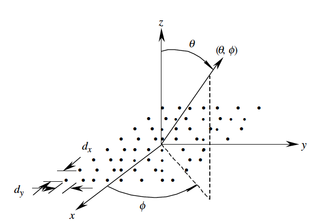 Figure 8 - Geometry of a planar array having arbitrary antenna elements with even spacing 1.
Beamforming
Beamforming enables spatial division multiple access, which is the splitting of a coverage area in the spatial domain by synthesized beams that service each individual user. $N$ beams at the base-station side are able to be supported by $N$ independent parallel DSP blocks in the transceiver. Smart antenna systems utilize knowledge of the DOA of all impinging signals in an active communication link and appropriate weights to control the radiation pattern towards the identified signls of interest while simultaneously placing nulls toward the non-SOI’s.
Direction of Arrival (DoA)
The DoA algorithm determines the direction of all incoming signals as a result of time delay measurements between different antenna elements. When an incoming signal impinges on an antenna array at some angle $(\theta,\phi)$ it creates a time delay relative to other antenna elements. This delay is a function of the array geometry, number of elements, and element spacing. DoA methods can be separated into four primary approaches:
- Conventional methods
- Subspace-based methods
- Maximum likelihood methods
- Integrated methods (hybrid approach of 1-3)
Conventional DoA is based on beamforming and null steering and do not use statistics of the received signal to synthesize the antenna pattern. The DoA in this method is obtained by determining the output power spectrum’s peaks after steering the beam in all desired search directions.
Subspace based DoA rely on the structure of the received data statistics to improve the resolution of the DoA method. The two popular approaches are MUSIC (MUltiple SIgnal Classification) and ESPRIT (Estimation of Signal Parameters via Rotational Invariance Technique). MUSIC exploits the eigenstructure of the input signal’s covariance matrix and provides information about the number of incident signals, their DoA’s, magnitudes, cross-correlations, noise, etc. Some of the drawbacks of a MUSIC based approach is the precision required for accurate array calibration, computational intensity, and inability to function when impinging signals are sufficiently correlated (often the case in multipath environments).
ESPRIT has several advantages over MUSIC such as being less computionally complex, requiring less memory to sample and store signals, more efficient steering vector search, and having no requirement of array calibration. This has become the algorithm of choice for subspace based DoA approaches.
Adaptive Beamforming
After the DoA information of all impinging signals is calculated, the DSPs controlling the smart antenna use an adaptive algorithm to steer the maximum radiation of the antenna towards the SOIs and dynamically add nulls to non-SOIs.
Optimal Beamforming Techniques
Optimal beamforming involves optimizing some cost function that inversely relates some performance masure to the array output. In this methods, there is some weight vector which minimizes some cost function (therefore maximizing the desired performance measure). The most common techniques are the Minimum Mean Square Error (MMSE), Maximum Signal-to-Noise Ratio (MSNR), and Minimum (noise) Variance(MV).
A particularly popular approach involves the minimization of the Mean Square Error (MSE) cost function. Deriving the weights to minimize the MSE involves first computing the error vector $\epsilon_k$ between the signal that is desired ($d_k$) and array’s output signal ($y_k$) as: \(\epsilon_k = d_{k} - \mathbf{w^{H}x_k} \tag{2}\)
From this error signal, the MSE cost function is expressed as:
\[\begin{aligned} J_{\mathrm{MSE}}\left(E\left[\varepsilon_k^2\right]\right) & =E\left[\left(d_k-\mathbf{w}^H \mathbf{x}_k\right)^2\right] \\ & =E\left[d_k^2-2 d_k \mathbf{w}^H \mathbf{x}_k+\mathbf{w}^H \mathbf{x}_k \mathbf{x}_k^H \mathbf{w}\right] \\ & =d_k^2-2 \mathbf{w}^H E\left[d_k \mathbf{x}_k\right]+\mathbf{w}^H E\left[\mathbf{x}_k \mathbf{x}_k^H\right] \mathbf{w} \end{aligned} \tag{3}\]Minimizing this cost function then includes taking the gradient of Eq. 3 and setting it equal to zero.
\[\min _{\mathbf{w}}\left\{J_{\mathrm{MSE}}\left(E\left[\varepsilon_k^2\right]\right)\right\} \Rightarrow \frac{\partial}{\partial \mathbf{w}}\left\{J_{\mathrm{MSE}}\left(E\left[\varepsilon_k^2\right]\right)\right\}=0 \tag{4}\]which when solved in terms of the weights leads to the optimal weight vector:
\[\mathbf{w_{opt}} = \mathbf{R_{xx}^{-1}r_{xd}} \tag{5}\]Eq. 5 represents the optimal array weight vector from an MMSE perspective.
Antenna Diversity
The key benefit of multi-antenna systems (MIMO: multiplie-input-multiple-output) is diversity.
Diversity can be broken down into spatial diversity, receive diversity, and transmit diversity.
Spatial Multiplexing
MIMO allows for spatial multiplexing which is the decomposition of a single high data rate stream into $M$ parallel data streams which can be independently coded and transmitted on separate antenna elements. This allows for enhanced spectral efficiency and throughput. Note that spatial multiplexing sacrifices the benefits of other diversity techniques in order to maximize throughput, since dedicated processing techniques on all antenna streams are used to allow for the datarate increase provided by spatial multiplexing.
Mobile Ad-Hoc Networks
A mobile ad-hoc network (MANET) is a collection of nodes that are wirelessly connected to form an extended communicaton link. This topology is able to rapidly change, and does not require a central control network to monitor connections in the mesh. This in contrast to cellular networks where a base station (eNodeB) has some centralized radio network controller (RNC) which has complete jurisdiction over a cellular network’s communication capabilities, access, and much more. Cellular networks also provide only single hop connectivity, whereas MANETs provide multi hop connectivity, whereby communication between Node A and Node B can be passed along by other members of the MANET even though the packets are not destined for them. This is illustrated in Fig. 8 below:
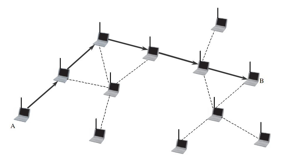 Figure 9 - A multihop manet. Communication between nodes A & B can be hopped by interconnecting nodes to extend communication range 1.
MANETs which pass information to interconnecting nodes are known as peer-to-peer networks and must operate according a certain set of rules (per each layer of the communication protocol) which spells out how information is to be organized, transmitted, and routed. Additionally, a communication medium in a peer-to-peer network is shared amongst frequency, space, and time. This leads to the need for multiple access techniques to allow multiple users to efficiently access the communication medium in a seamless manner. The different types of multiple access include
- Time Division Multiple Access (TDMA)
- Frequency Division Multiple Access (FDMA)
- Code Division Multiple Access (CDMA)
- Space Division Multiple Access (SDMA)
MANETs and Smart Antennas
Smart antennas allow for dynamic control of radiation patterns towards desired users while also providing suppression against unwanted interferers. This improves link robustness (capacity, throughput) and also allows a MANET topology to be dynamic as the antenna patterns themselves are reconfigurable. MANETs use modern communication system techniques such as smart antenna systems to improve network spectral efficiency and throughput. They allow multiple users to communicate with each other at a given time due to the SDMA of separate antenna beams. An omnidirectional network would cause packet collisions amongst neighbors and greatly reduce network throughput by forcing users to wait extra long until their allocated timeslot is collision free from other users (TDMA). This is shown in Fig. 9.
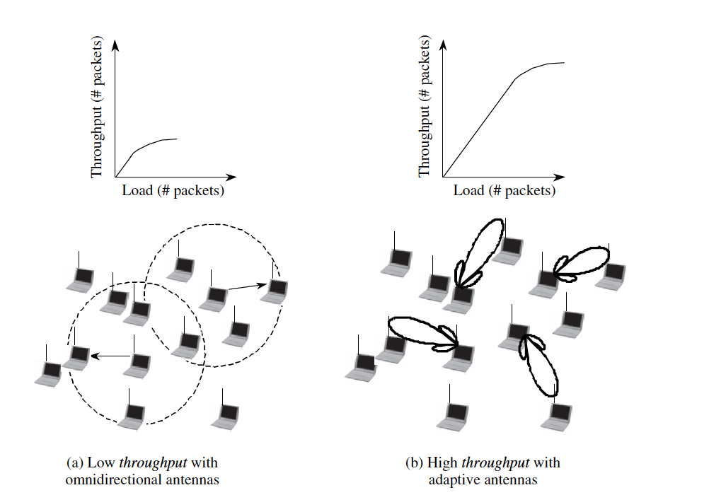 Figure 10 - MANET capacity comparison with one network having omnidirectional radiators and the other having a smart antenna system 1.
MANET Protocols
As previously mentioned, MANETs utilize agreed upon protocols which spell out how a communication medium is access, how communication takes place, how errors are handles, and how data is routed. There are multiple layers in an OSI (Open Systems Interconnection) model, but the lowest 2 layers are what govern the way a specific system transmits/receives information, how it is encoded, how multiple users are dealt with, and more. The upper layers (3-7) are abstractions for data routing/transport that allows high level entities (Application Layer) to access the internet or some other entity which allows generalized communication query/responses between clients and servers. For the purpose of smart antenna discussion, the two relevant layers are the PHY (Physical Layer) and the MAC (Medium Access Control). An example of a widespread MAC protocol used in MANETs is that of IEEE 802.11 - the IEEE standard for WLAN/WiFi systems.
A brief overview of the MAC protocol for IEEE 802.11 follows with relations to smart antenna systems spelled out (refer to Fig. 10)
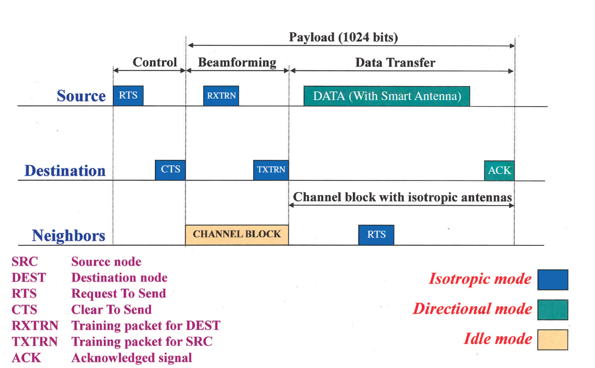 Figure 10 - Protocol timing diagram of the IEEE 802.11 MAC 1.
- Channel Access: A source node (SRC) has a packet to transmit to a destination (DEST) which is within a single hop, it first senses the activity of the communication channel and determines if the channel is busy or not. When the channel is busy, the node is idle. Once the channel is available, the SRC broadcasts an RTS (request to send) using the smart antenna in an omnidirectional mode. The DEST node receives the RTS and will retransmit an omnidirectional CTS (clear to send) if it is ready to receive information from the SRC.
- Beamforming: When all nodes in the cell receive the CTS broadcast, they will idle until beamforming is complete before accessing the channel again. After CTS is received by the SRC, it transmits training packets to DEST in omnnidirectional mode. DEST then uses this training data to determine the AoA and determines the weights for optimal beamforming. After this, DEST will transmit its own training packets to the SRC using its optimal beamformed antenna pattern. The SRC will then use this training data from DEST to compute its own AoA and obtain optimal weights to beamform back.
- Data Transfer: After SRC & DEST have directed their patterns towards each other, beamforming is complete and DATA is ready to be transferred. At this point, the channel is free for other nodes to broadcast omnidirectional RTS/CTS messages. If these neighboring broadcasts cause interference between two nodes that have already established optimal beams for transmission/reception, a new set of beams will be generated to place nulls on the other node’s interfering signals. After DATA is completely transmitted, the DEST sends an ACK (acknowledgement) to indicate it has successfully received the packet. If no ACK is transmitted after a certain amount of time, the SRC may retransmit DATA again. Additionally, DEST may identify errors in the received packet and fail the CRC (cyclic redundancy check) in which case it will transmit a NACK signal.
References